555 Timer Schematic Diagram : Monostable multivibrator (mmv) mode of 555 timer ic is also called single shot mode.. The 555 timer delay before turn on circuit we will build is shown below. 555 timer ic remains in stable state until the external triggering is applied. So we have a signal with a frequency of about 60hz. Simple 555 timer circuits & projects. Adjustable on off timer(using 555 astable mode) in this circuit a timer with cyclic on off operations is designed.
In this circuit, after you press the button once, the led will light up then turn off. If a 10uf timing capacitor is used, calculate the value of the resistor required to produce a minimum output time delay of 500ms. We would like to show you a description here but the site won't allow us. Working modes of 555 timer ic. A collection of 555 circuits using the 555 timer as an astable oscillator with different duty cycles.
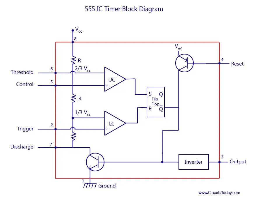
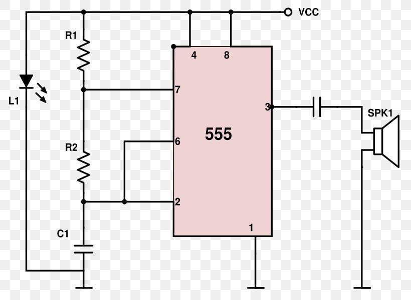
555 Timer Ic Block Diagram Working Pin Out Configuration Data Sheet from www.circuitstoday.com 555 timer ic schematic diagram 555 timer schematic. We connect a 100μf capacitor to the positive voltage supply and then to pin 2. Use the diagram below to connect the circuit: We did not find results for: Each mode of operation indicates a circuit diagram and its output. The values of r1 and c1 determine how long the output will remain high. The 555 timer, designed by hans camenzind in 1971, can be found in many electronic devices starting from toys and kitchen appliances to even a spacecraft. 13+ 555 monostable circuit diagram.
The reset input current draw illustrates the need for a current limiting resistor as shown in some of the preceding circuits.
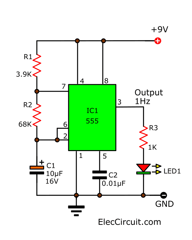
Working modes of 555 timer ic. In this circuit, after you press the button once, the led will light up then turn off. The next diagram shows the basic current consumption of 555 timer chips from different manufacturers. If you are a beginner in electronics, you should learn the basics about a 555 timer ic, before you attempt to build 555 timer circuit or a full 555 timer project. As discussed in the above section, the ic is in its standard monostable mode. Resistive network consists of three equal resistors and acts as a voltage divider. Here we have controlled the output frequency of the pwm signal by selecting resistor rv1 and capacitor c1. Astable mode can produce digital square waveforms that go back and forth between high and low. In this mode, the circuit of the ic 555 timer produces the continuous pulses with exact frequency primarily based on the value of the two resistors and. In this pwm generater circuit, as we mentioned above we have used 555 timer ic for generating pwm signal. 555 timer timers, as the name specified, are the electronics circuits used for measuring time intervals.this tutorial provides sample circuits to set up a 555 timer in monostable, astable, and bistable modes as well as an in depth discussion the 555 timer uses several transistors to construct its comparators (see the image notes in fig 3), so in the. 555 timer, as the name specified, are the electronics circuits used for measuring time intervals.in this article, we will cover about 555 timers. 555 timer circuit | circuit diagram.
We would like to show you a description here but the site won't allow us. 555 timer, as the name specified, are the electronics circuits used for measuring time intervals.in this article, we will cover about 555 timers. After one minute of time duration, the led will automatically turn on. The breadboard schematic of the above circuit is shown below. The 4rth circuit diagram shows the standard ic 555 adjustable timer circuit having two sets of timing ranges and an output relay for toggling the desired load.
555 Timer Ic Mosquito Electronic Circuit Electronics Circuit Diagram Png 800x600px 555 Timer Ic Area Circuit from img.favpng.com The 555 timer starts timing when switched on. Lm555 timer 1 features 3 description the lm555 is a highly stable device for generating 1• direct replacement for se555/ne555 accurate time delays or oscillation. There are simple circuits for beginners and advanced engineers. 555 datasheet 555 duty cycle 555 metronome 555 reset function 555 time delay relay inverted 555 timer pulse generator. Connection using a resistor is not recommended to avoid heating up of the ic because of the stray. Some devices will not function properly if the current to the threshold input is not restricted. If a 10uf timing capacitor is used, calculate the value of the resistor required to produce a minimum output time delay of 500ms. The block diagram of a 555 timer is shown in the above figure.
555 ic timer block diagram 555 ic timer block diagram.
We have used a variable resistor in place of fixed resistor for changing. Some devices will not function properly if the current to the threshold input is not restricted. There are simple circuits for beginners and advanced engineers. 555 timer is an industrial standard ic existing from early days of ic. Here we have controlled the output frequency of the pwm signal by selecting resistor rv1 and capacitor c1. After one minute of time duration, the led will automatically turn on. A monostable 555 timer is required to produce a time delay within a circuit. When triggered by a button integrated in the circuit relay 555 timer is energized and immediately set is full when you leave the ignition again. 500ms is the same as saying 0.5s so by rearranging the formula above, we get the calculated value for the resistor, r as: If a 10uf timing capacitor is used, calculate the value of the resistor required to produce a minimum output time delay of 500ms. It is a highly stable integrated circuit that can produce accurate time delays and oscillations. Once this switch is pushed, the circuit pulls its output to a. 555 timer ic schematic diagram.
We did not find results for: Some devices will not function properly if the current to the threshold input is not restricted. The 555 timer is the one of the most versatile linear hybrid integrated circuit (ic) which is used in variety of pulse generation, timer and oscillator applications. As discussed in the above section, the ic is in its standard monostable mode. Let us discuss in detail about this circuit.
How Does Ne555 Timer Circuit Works Datasheet Pinout Eleccircuit Com from www.eleccircuit.com We did not find results for: The circuit mentioned here is a ten minutes timer, after pusing. 555 timer ic remains in stable state until the external triggering is applied. As discussed in the above section, the ic is in its standard monostable mode. 555 timer, as the name specified, are the electronics circuits used for measuring time intervals.in this article, we will cover about 555 timers. Each mode of operation indicates a circuit diagram and its output. Monostable multivibrator (mmv) mode of 555 timer ic is also called single shot mode. The 4rth circuit diagram shows the standard ic 555 adjustable timer circuit having two sets of timing ranges and an output relay for toggling the desired load.
The 4rth circuit diagram shows the standard ic 555 adjustable timer circuit having two sets of timing ranges and an output relay for toggling the desired load.
If a 10uf timing capacitor is used, calculate the value of the resistor required to produce a minimum output time delay of 500ms. Some devices will not function properly if the current to the threshold input is not restricted. Referring to the timing diagram in figure 3, a low voltage pulse applied to the trigger input (pin 2) causes the output voltage at pin 3 to go from low to high. This integrated circuit can be used in a variety of ways from which the basic one is to produce accurate and stable delays in electronic circuits.additionally, it is available in 8 pin dip and 14 pin dip. Above schematic diagram shows the 555 timer monostable multivibrator circuit. The values of r1 and c1 determine how long the output will remain high. Monostable multivibrator (mmv) mode of 555 timer ic is also called single shot mode. As discussed in the above section, the ic is in its standard monostable mode. Lm555 timer 1 features 3 description the lm555 is a highly stable device for generating 1• direct replacement for se555/ne555 accurate time delays or oscillation. 555 timer ic schematic diagram 555 timer schematic. Ground (gnd) it's the common ground point of the circuit. We connect a 100μf capacitor to the positive voltage supply and then to pin 2. The 4rth circuit diagram shows the standard ic 555 adjustable timer circuit having two sets of timing ranges and an output relay for toggling the desired load.
500ms is the same as saying 05s so by rearranging the formula above, we get the calculated value for the resistor, r as: 555 timer schematic. In this mode, the circuit of the ic 555 timer produces the continuous pulses with exact frequency primarily based on the value of the two resistors and.


0 Komentar